


What Is Cutting Tool Geometry?
In precision machining, the performance of a cutting tool depends heavily on its design. The angles, edges, and shapes of a tool determine how efficiently it cuts material, controls chip formation, and maintains dimensional accuracy. This design structure is known as cutting tool geometry, and it plays a crucial role in determining machining performance.
Proper tool geometry helps reduce cutting forces, improve surface finish, and extend tool life. Whether machining components on a CNC milling machine or a turning setup involving lathe cutting tool geometry, selecting the right geometry ensures efficient material removal and consistent machining results.
Understanding the Angles and Shapes of Cutting Tools
Cutting tools are designed with specific angles and shapes that influence how the tool interacts with the workpiece. These angles guide chip flow, determine cutting forces, and help maintain stability during machining operations.
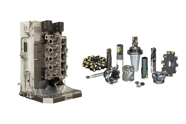
The geometry of a cutting tool includes several important elements such as rake angles, clearance angles, helix angles, and cutting edges. Each of these elements contributes to the tool’s ability to cut effectively without causing excessive heat, vibration, or tool wear.
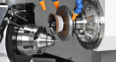
The Role of Milling Cutter Tool Geometry in Machining Efficiency
The milling cutter tool geometry directly impacts how efficiently a milling operation can remove material. Well-designed tool geometry ensures smooth chip evacuation, reduces friction, and maintains cutting stability.
Optimized geometry allows manufacturers to achieve faster machining speeds while maintaining accuracy. This is particularly important in industries such as automotive and aerospace, where productivity and precision are equally critical.
How Tool Geometry Influences Material Removal
The design of the cutting tool geometry determines how material is sheared from the workpiece. Proper geometry allows chips to flow away smoothly, preventing tool clogging and reducing heat buildup.
Incorrect tool geometry, on the other hand, can lead to excessive cutting forces, poor chip formation, and faster tool wear. For this reason, understanding the geometry of milling cutter designs is essential when selecting tools for specific machining applications.
Key Elements of Cutting Tool Geometry
Several elements define the overall geometry of a cutting tool. These elements work together to control chip flow, reduce friction, and maintain cutting efficiency.
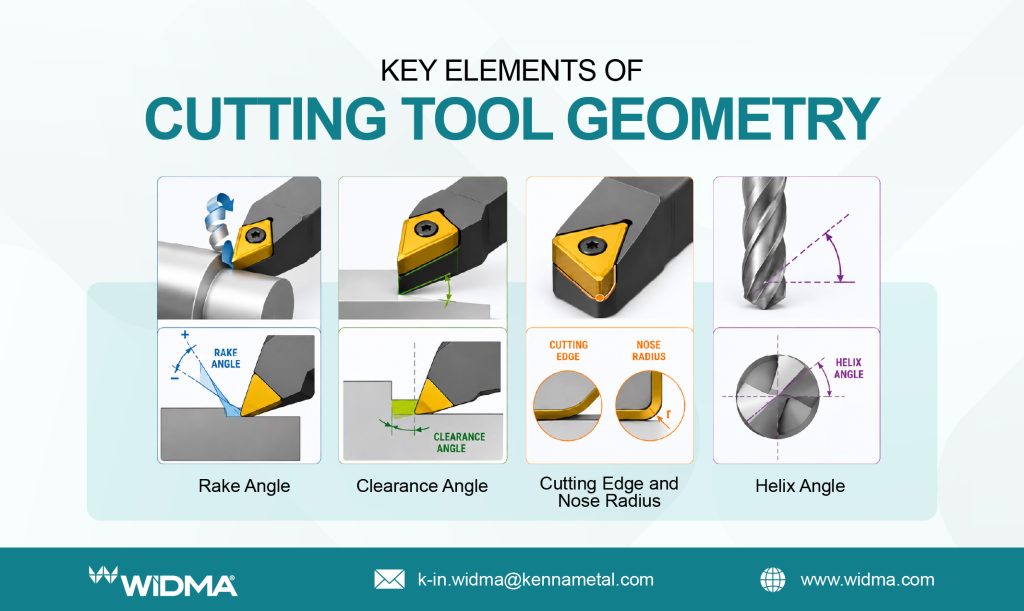
Rake Angle – Controlling Chip Flow and Cutting Forces
The rake angle is the angle between the cutting edge and the surface of the workpiece. It plays a critical role in directing chip flow and controlling cutting forces.
A positive rake angle reduces cutting forces and improves chip removal, while a negative rake angle strengthens the cutting edge for heavy-duty machining operations.
Clearance Angle – Preventing Tool-Workpiece Interference
The clearance angle ensures that the tool does not rub against the workpiece surface during machining. By providing space between the tool and the workpiece, it reduces friction and heat generation.
Proper clearance angle design is essential for maintaining tool life and ensuring consistent machining quality.
Cutting Edge and Nose Radius – Balancing Strength and Precision
The cutting edge is responsible for removing material from the workpiece. The nose radius at the tip of the tool influences both surface finish and tool strength.
A larger nose radius improves surface finish but may increase cutting forces, while a smaller radius provides better precision for detailed machining tasks.
Helix Angle – Optimizing Chip Evacuation
The helix angle refers to the angle of the cutting edge relative to the tool axis. It plays a key role in chip evacuation and cutting stability.
Higher helix angles are often used in high-speed machining because they promote smoother chip flow and reduce vibration during milling operations.
How Cutting Tool Geometry Affects Cutting Performance
The geometry of cutting tools directly impacts machining performance, influencing everything from cutting forces to surface finish quality.
Reducing Cutting Forces for Smoother Operations
Proper cutting tool geometry helps reduce the force required to remove material. Lower cutting forces result in smoother machining operations and improved machine stability.
This is particularly important when machining complex components that require precise dimensional control.
Enhancing Surface Finish Quality
Tool geometry plays a significant role in determining the final surface finish of machined parts. Optimized tool angles ensure uniform cutting action, reducing tool marks and surface imperfections.
As a result, manufacturers can achieve higher-quality finishes without requiring extensive post-processing.
Improving Tool Life and Durability
Correct geometry distributes cutting loads more evenly across the tool, reducing wear and preventing premature tool failure. This leads to longer tool life and reduced tooling costs.
Minimizing Heat Generation During Machining
Heat generation is a major challenge in machining processes. Well-designed geometry improves chip evacuation and reduces friction, helping maintain stable cutting temperatures.
Cutting Tool Geometry and Different Workpiece Materials
Different materials require different cutting tool geometries to achieve optimal machining results.
Optimal Cutting Tool Geometry for Soft Materials
Soft materials such as aluminium and mild steel benefit from tools with higher rake angles and sharper cutting edges. These features reduce cutting forces and allow faster machining speeds.
Tool Geometry Requirements for Hard and Abrasive Materials
Harder materials, such as stainless steel or hardened alloys, require stronger tool edges and lower rake angles. This helps prevent tool chipping and ensures durability during heavy machining operations.
Influence of Tool Geometry on Chip Formation Across Materials
Chip formation varies significantly depending on the workpiece material. Adjusting tool geometry ensures proper chip breaking and evacuation, which improves overall machining efficiency.
Tool Nose Radius Selection Based on Workpiece Material
Selecting the correct nose radius is important for balancing surface finish and tool strength. Larger radii are typically used for finishing operations, while smaller radii are better suited for precision cutting tasks.
Selecting the Right Cutting Tool Geometry for Your Application
Choosing the correct tool geometry is essential for achieving the best machining performance.
Matching Geometry to Machining Operations
Different machining operations, such as turning, milling, and drilling, require specific geometries to achieve optimal results.
Evaluating Production Speed and Tolerance Requirements
Manufacturers must consider both production speed and tolerance levels when selecting tool geometry. High-speed operations may require specialized tool designs to maintain stability.
Choosing Geometry for High-Volume vs. Low-Volume Runs
High-volume manufacturing often prioritizes durability and repeatability, while low-volume production may focus more on precision and flexibility.
Adapting Tool Design for Multi-Material Applications
When machining different materials on the same machine, adaptable tool geometries can help maintain consistent performance without frequent tool changes.
Conclusion
Understanding cutting tool geometry is essential for achieving efficient and accurate machining operations. From controlling chip flow to improving surface finish and extending tool life, the geometry of cutting tools directly influences manufacturing performance.
By selecting the right geometry for specific machining applications, manufacturers can optimize productivity, improve component quality, and ensure reliable machining processes across a wide range of materials and industries.
FAQ
1. What is cutting tool geometry, and why is it important in machining?
Cutting tool geometry refers to the design and angles of a cutting tool that determine how it removes material, controls chip flow, and maintains machining accuracy.
2. How does the geometry of the milling cutter affect cutting performance and efficiency?
The geometry of milling cutter designs influences chip evacuation, cutting forces, and surface finish, directly impacting machining performance.
3. What are the main components of cutting tool geometry?
Key components include rake angle, clearance angle, cutting edge, nose radius, and helix angle.
4. How should cutting tool geometry be selected for CNC machining operations?
Tool geometry should be chosen based on machining operation, material type, required tolerance levels, and production volume.